Valve cavitation is a serious hydraulic issue that often starts as “minor noise” but can quickly undermine equipment life, process stability, and maintenance budgets. In high pressure-drop services, partially throttled lines, and processes with frequent flow changes, cavitation typically manifests as pitting on internal trim, loss of tight shutoff, increased vibration, and sudden performance degradation. The key point is this: cavitation is rarely solved by “replacing one part.” Sustainable control requires a combined approach—proper valve selection, correct sizing (Cv), disciplined management of pressure drop, sound piping practices, and a maintenance strategy aligned with operating data.
This guide explains how to reduce valve cavitation risk with practical, technically correct steps—without turning the discussion into impenetrable jargon. You will also see how common valve families and line components—forged valves, gate valves, globe valves, check valves, ball valves, and filters/strainers—connect logically to cavitation prevention. If you suspect cavitation in your plant, use the checklist at the end to build an actionable improvement plan today and stabilize your line before unplanned downtime escalates.
What is valve cavitation?
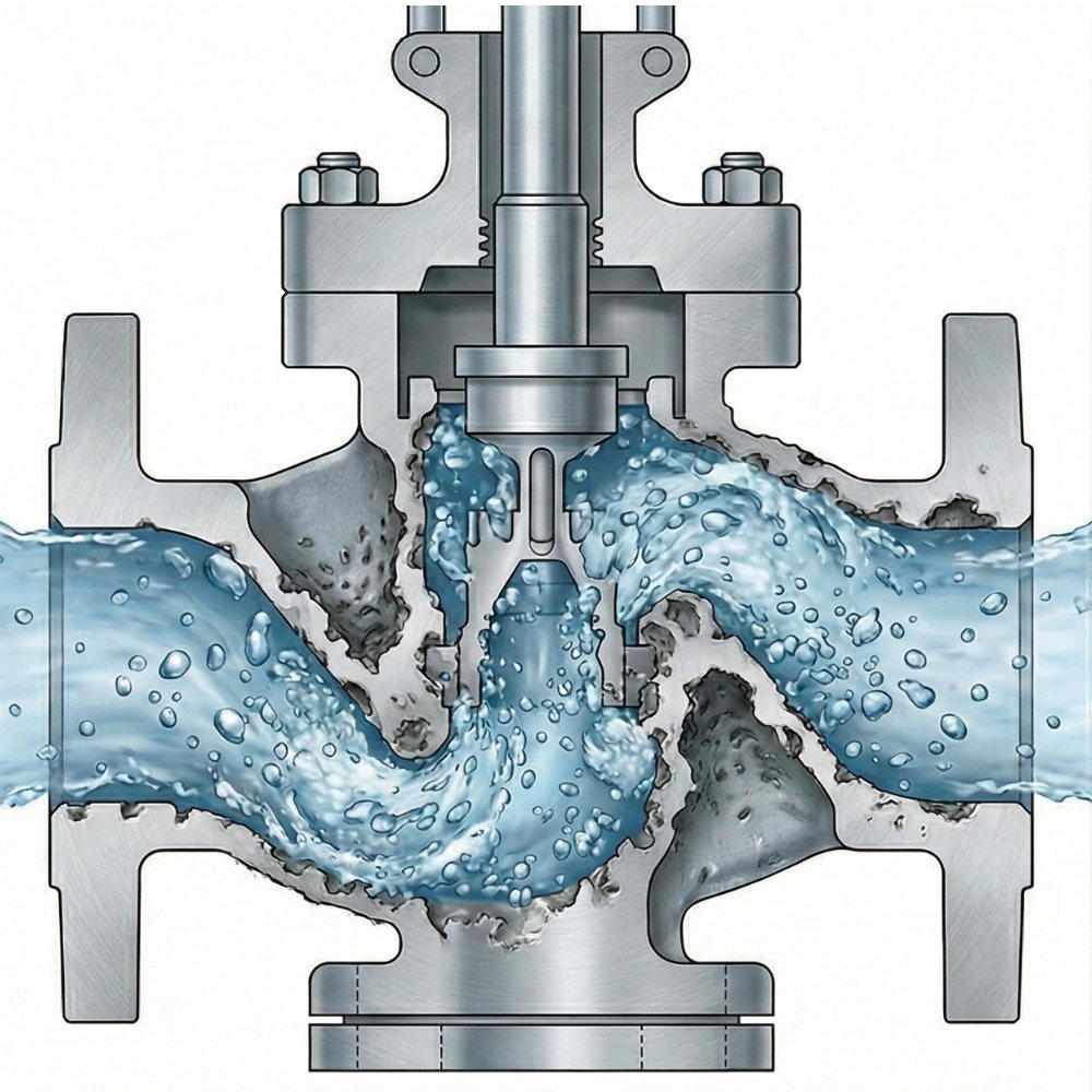
Valve cavitation occurs when the local static pressure within the valve (typically in high-velocity, constricted regions) drops below the fluid’s vapor pressure, causing vapor bubbles to form. As the flow moves into a higher-pressure region downstream, these bubbles collapse violently, generating micro-jets and shock waves. The repeated collapse events create characteristic surface damage—pitting and “honeycombing”—especially on trim and seating areas.
Cavitation is not only a material-loss mechanism. It is also an operational reliability issue because it can drive:
- Higher acoustic emissions and vibration (accelerating fatigue of mechanical joints)
- Control instability (oscillation/hunting around the setpoint)
- Reduced shutoff performance (leakage and integrity concerns)
- Shorter maintenance intervals and increased likelihood of forced outages
In short: cavitation may be a hydraulic phenomenon, but its business impact is measured in availability, safety margins, and total cost of ownership.
Where cavitation is most common
Cavitation is most frequently observed in high ΔP services, in valves used for throttling (especially in control applications), and in systems with rapidly varying flow. Increased temperature typically raises vapor pressure and can move the cavitation threshold into the operating envelope—meaning the same valve and pressure drop can behave very differently as temperature changes.
Why does valve cavitation happen, and how do you recognize it?
The root cause is the lowest local pressure point inside the valve. This minimum pressure often occurs near the seat/trim region, at sharp contractions, or where jets and recirculation zones develop. Cavitation risk typically increases under the following conditions:
- High pressure drop (ΔP): Breaking too much pressure in a single stage is a classic trigger.
- High flow velocity: Higher velocity generally means lower static pressure in the vena contracta.
- Low downstream pressure: Lower recovery pressure can intensify collapse energy.
- Higher temperature: Elevated vapor pressure reduces the margin to cavitation inception.
- Incorrect sizing:
- Undersized valve → excessive velocity and aggressive pressure recovery
- Oversized valve → poor controllability and operation at small openings, often re-creating severe conditions
Field diagnosis: what does cavitation “sound like”?
Cavitation is often described as a “gravel” or “crackling” sound. Typical accompanying symptoms include:
- High-frequency vibration in the valve body and adjacent piping
- Local temperature rise due to turbulence and energy dissipation
- Sudden loss of effective capacity (apparent Cv drift)
- Premature deterioration of tightness (seat and seal damage)
These indicators alone are not a definitive diagnosis. The most reliable approach is to correlate symptoms with operating data (upstream/downstream pressure, flow rate, and temperature) and inspect internal trim during planned maintenance.
Cavitation vs. flashing: the critical distinction
Cavitation is frequently confused with flashing, but the mitigation strategy differs:
- Cavitation: Vapor bubbles form and then collapse as pressure recovers. Damage is often most severe where collapse occurs—typically near trim exit and immediately downstream.
- Flashing: Pressure drops below vapor pressure and part of the liquid transitions to vapor; if downstream pressure does not rise above vapor pressure, the vapor phase persists. Damage is then driven by two-phase, high-velocity erosive flow, and standard “anti-cavitation” trims may not be sufficient.
A practical rule of thumb: if downstream pressure does not recover above vapor pressure under expected conditions, flashing is likely. This distinction directly influences trim selection, staging strategy, and whether a different process scheme is required.
Preventing cavitation through correct valve selection
One of the strongest levers for reducing cavitation is matching the valve type to the duty. In many plants, the problem is not that the valve “doesn’t work”—it is that the valve is used in the wrong service. A well-structured portfolio that includes forged valves, gate valves, globe valves, check valves, ball valves, and filters/strainers supports proper engineering alignment across isolation, throttling, non-return, and protection functions.
The table below summarizes common field patterns:
| Valve / component | Typical cavitation risk | Best-fit duty | Cavitation-prevention approach |
|---|---|---|---|
| Gate valve | Medium/High (if throttled) | On/off isolation (full open/closed) | Avoid throttling; do not break high ΔP in one point |
| Globe valve | Medium (low with correct trim) | Throttling, flow control, pressure reduction | Anti-cavitation trim, multi-stage pressure reduction, correct Cv |
| Ball valve | Medium (risky in high ΔP throttling) | Fast on/off, low pressure loss | Characterized/V-port solutions where throttling is required; correct sizing |
| Check valve | Low/Medium (higher during transients) | Prevent reverse flow | Non-slam designs, water hammer control, correct placement |
| Filters/strainers | Indirect (increases ΔP) | Equipment protection, particulate capture | Low ΔP design, monitor clogging, routine cleaning |
| Forged valves (body/trim strategy) | Service-dependent | High-pressure / severe service | Robust materials/coatings, precision machining, disciplined testing |
Gate valves: a common “hidden trigger”
Gate valves are isolation valves. The most frequent mistake is using a gate valve as a throttling device for extended periods. At partial openings, the flow path creates a restrictive, high-velocity region; static pressure drops locally and cavitation can initiate. The practical fix is straightforward: if throttling is required, use a valve designed for control—typically a properly selected globe valve (or a suitably characterized solution), and operate the gate valve in full open/full closed mode.
Globe valves: the platform for controlled pressure reduction
Globe valves are often preferred for throttling because they can manage flow direction changes and offer trim options tailored to control duties. However, not every globe valve is inherently cavitation-resistant. In high ΔP services, the following become decisive:
- Proper trim geometry (cage-guided, multi-hole, multi-stage designs)
- Correct Cv selection (avoid both undersizing and oversizing)
- When needed, staged pressure reduction (do not force all ΔP across one trim)
Ball valves: excellent for on/off—throttle with care
Ball valves are widely used for low pressure loss and fast operation. Depending on service requirements, floating or trunnion-mounted configurations are selected. From a cavitation perspective, the critical issue is prolonged throttling at high ΔP with a standard ball/seat geometry, which can drive turbulent jets and localized low-pressure zones near the seat. If throttling is unavoidable, a characterized approach (e.g., V-port-style behavior) and careful sizing are typically required.
Check valves: transient-driven cavitation risks
Check valves are not usually the primary location for steady-state cavitation. The bigger risk comes from transients—rapid closure, sudden pump trips, or flow reversals that create pressure oscillations (water hammer). Local pressure can momentarily drop enough to form cavitation pockets. Using non-slam designs, controlling closure dynamics, and ensuring correct piping layout and velocities are the practical countermeasures.
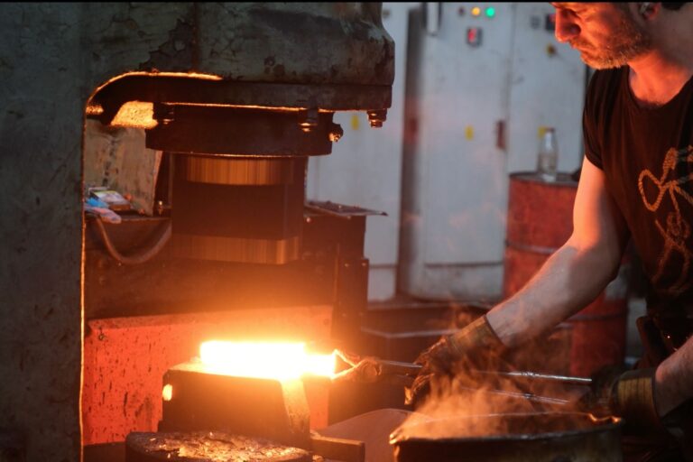
Forged valves and material strategy for severe service
Cavitation is often preventable, but in truly severe services the engineering objective may shift toward controlling impact and maximizing service life. Forged valve construction can provide advantages in body integrity, material homogeneity, and mechanical robustness, particularly in high pressure and critical duties.
To improve resistance against cavitation’s repeated micro-impacts, common engineering strategies include:
- Trim material selection: hardened stainless steels and erosion-resistant alloys where applicable
- Hardfacing and surface treatments: to increase erosion/cavitation resistance of critical edges and seating surfaces
- Precision machining and seating quality: poor seating can increase micro-leakage, turbulence, and local pressure fluctuations, accelerating cavitation damage
The operational reality is simple: good materials do not compensate for poor hydraulics. But when correct hydraulic design is combined with a robust forged body/trim strategy, service life can increase dramatically.
Filters/strainers and piping: managing pressure losses
Filters and strainers (including common Y-type configurations) protect valves and equipment from particulate contamination. However, if they are poorly selected or allowed to clog, they can introduce significant additional pressure loss in the line. That added ΔP reduces downstream pressure margin and can push a throttling valve into cavitation conditions. In other words, a properly maintained strainer is protective; a neglected strainer can become a cavitation enabler.
Three practical rules that consistently work in the field:
- Track strainer ΔP: differential pressure monitoring (or routine measurement) helps detect clogging early.
- Select for allowable pressure loss: avoid “smallest possible” strainers; size based on flow and permissible ΔP.
- Consider location relative to the valve: upstream restrictions can shift the critical low-pressure zone into or near the valve.
Piping geometry also matters. Sudden contractions/expansions, aggressive elbows, and insufficient straight-run lengths can increase turbulence and amplify the load on the valve. Simple layout improvements—proper reducers, smoother transitions, or better placement—can materially change cavitation behavior.
Anti-cavitation engineering: staged pressure reduction
For high ΔP applications, the most reliable strategy is to avoid “single-point” energy dissipation and instead stage the pressure reduction in a controlled manner. The main approaches are:
1) Multi-stage trim and energy dissipation
In globe-valve control duties, multi-hole and cage trims distribute the flow into many small jets, reducing local pressure dips and lowering bubble collapse intensity. The result is less concentrated damage and improved service life.
2) Series elements (valve/orifice combinations)
In some processes, two valves in series—or a valve combined with an orifice—can share the pressure drop. The benefit is lower ΔP per element; the trade-off is added complexity and the need for coordinated sizing and control logic.
3) Increasing downstream backpressure
Where the process allows, adding controlled backpressure downstream can significantly reduce cavitation intensity—not necessarily eliminating cavitation inception, but reducing collapse energy and damage rate.
4) Correct sizing (Cv) and control characteristic
Undersizing drives excessive velocity and aggressive pressure recovery. Oversizing often forces operation at very small openings, which can be equally problematic. Cv selection should therefore be performed not only to meet flow demand, but also to maintain cavitation margins within acceptable limits.
Conclusion and a fast field checklist
Valve cavitation is a high-impact reliability risk—but it is manageable with the right approach. The winning formula is consistent across industries: validate operating conditions, apply the correct valve type to the duty (gate for isolation, globe for controlled throttling/ΔP reduction, ball for fast on/off with appropriate characterization if throttling is required, check valves for transient control), stage pressure reduction when necessary, manage strainer pressure loss, and align materials/trim with severity.
Use the nine steps below as a rapid on-site cavitation assessment:
- Record upstream pressure, downstream pressure, flow rate, and temperature at the suspected cavitation point.
- Confirm whether the valve is throttling; if a gate valve is being used for throttling, evaluate a duty change.
- Determine whether a single valve is absorbing most of the ΔP; if yes, assess staging options.
- For globe valves, verify whether anti-cavitation trim is required for the actual ΔP and recovery conditions.
- If a ball valve is held partially open for long periods, evaluate characterized solutions and re-sizing.
- Check for water hammer indicators near check valves; review non-slam performance and installation geometry.
- Verify differential pressure across filters/strainers; if elevated, adjust cleaning frequency and sizing strategy.
- Trend noise/vibration; increasing levels justify earlier trim/seat inspection.
- For recurring failures, reassess severe-service materials, hardfacing/coatings, and a forged-valve strategy.
If valve cavitation remains a recurring issue, avoid the cycle of “replace and repeat.” Consolidate operating data, valve selection, piping losses, and maintenance history into a single engineering action plan. If you share your operating conditions (P1/P2, flow rate, temperature, valve type and size), we can map a practical solution scenario that reduces valve cavitation risk and improves uptime with measurable, plant-ready steps.


Contact Us Now
Reach out to our expert team today for tailored valve solutions for your projects.